Products Description
The MKZ806 servo amplifier adopts a mature, stable, and reliable circuit modular design, mainly used for driving electro-hydraulic servo valves (MFB: mechanical force feedback, EFB: electric feedback type, with built-in controller proportional solenoid valve, etc.) in industrial hydraulic systems. The working principle of the MKZ806 servo amplifier is shown in the schematic diagram. It can convert the standard signals commonly used in industrial hydraulic systems on site: 0~± 10mA (± 100mAmax), PLC output 0~± 10V, 4-20mA, after conditioning, into the required voltage or current drive signal and control its proportional output: 4-20mA; 0~± 10V; 0~± 100mA.
The MKZ806 servo amplifier is equipped with an active first-order low-pass filter with 5 selectable cutoff frequencies. The desired cutoff frequency value can be obtained by combining the selection switches to eliminate noise in the input signal and provide high anti-interference ability.
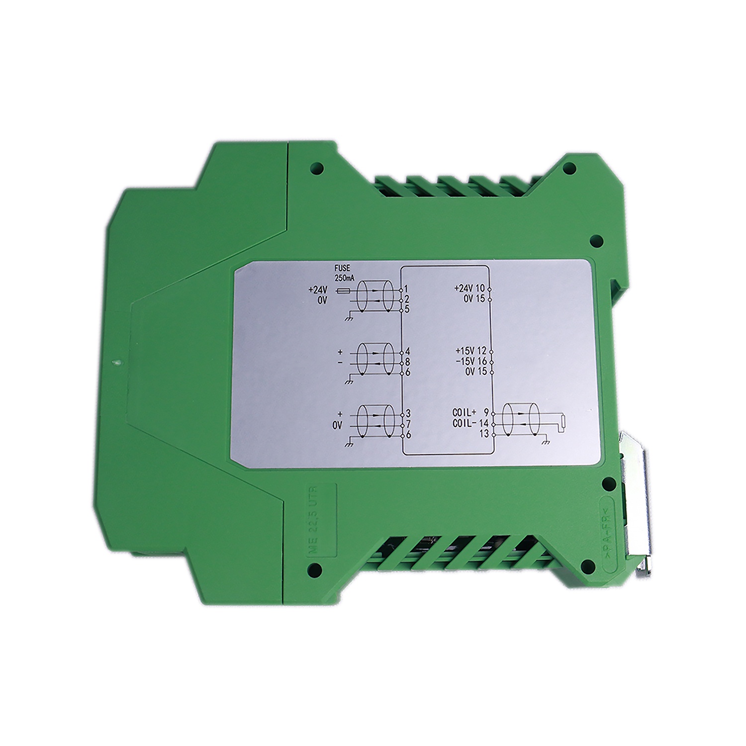
The MKZ806 servo amplifier is equipped with+24V and ± 15V auxiliary power supply and control command input signals for the electric feedback type electro-hydraulic servo valve. When the mechanical force feedback type electro-hydraulic servo valve needs to be replaced in situ by the electric feedback type electro-hydraulic servo valve, there is no need to replace the original valve servo amplifier. Simply input the current signal of the original driving valve to the MKZ806 servo amplifier for use.
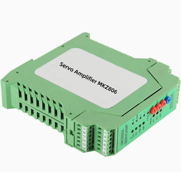
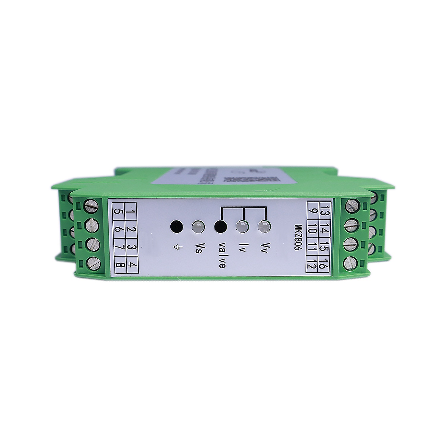
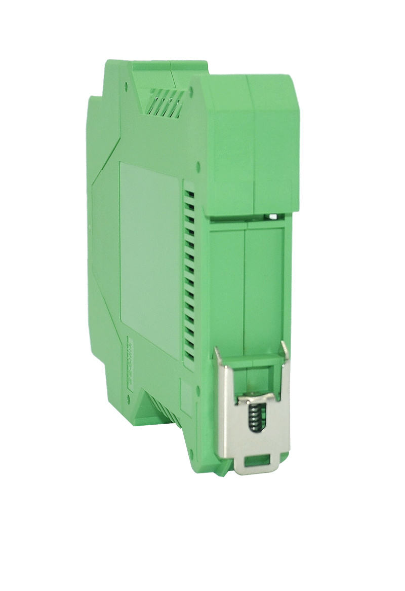
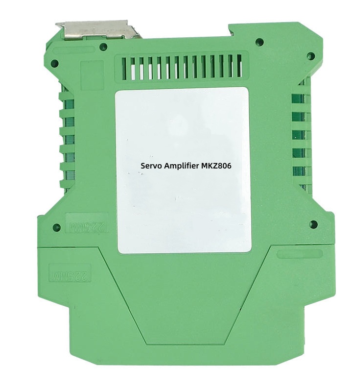
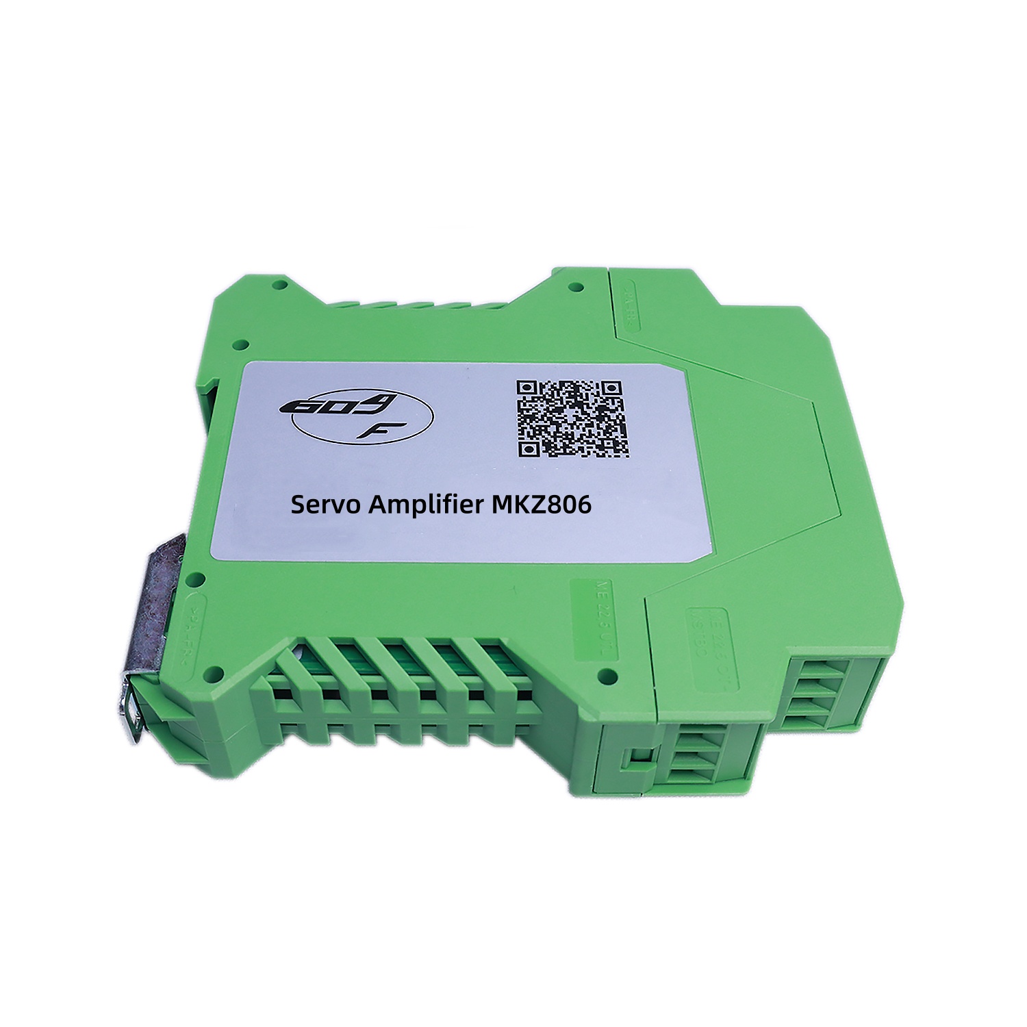
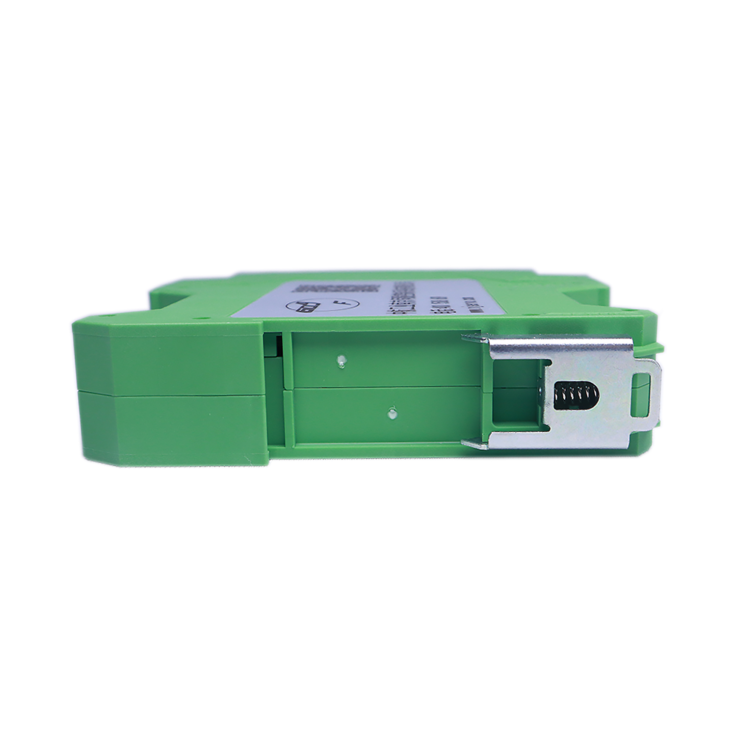
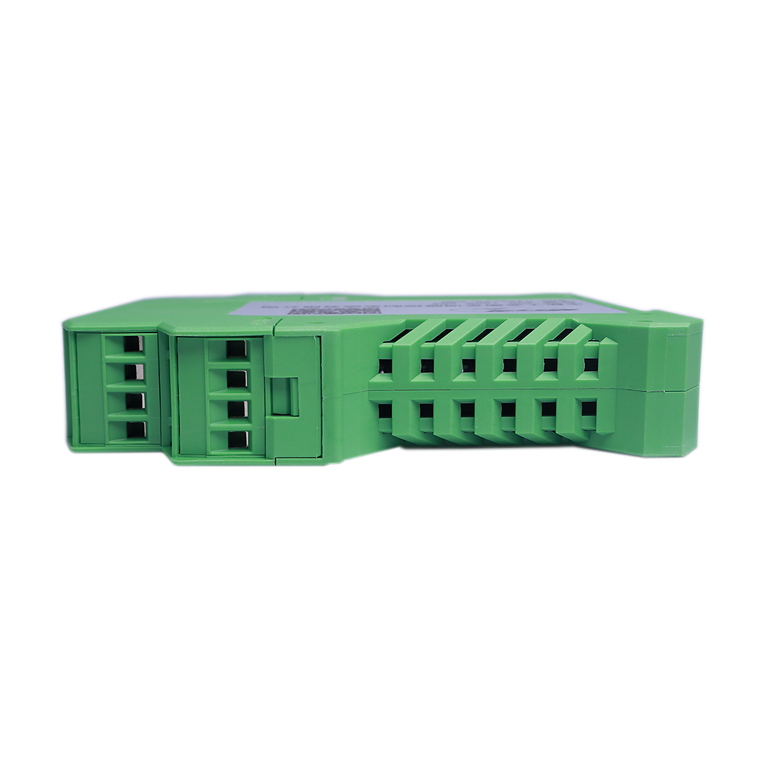
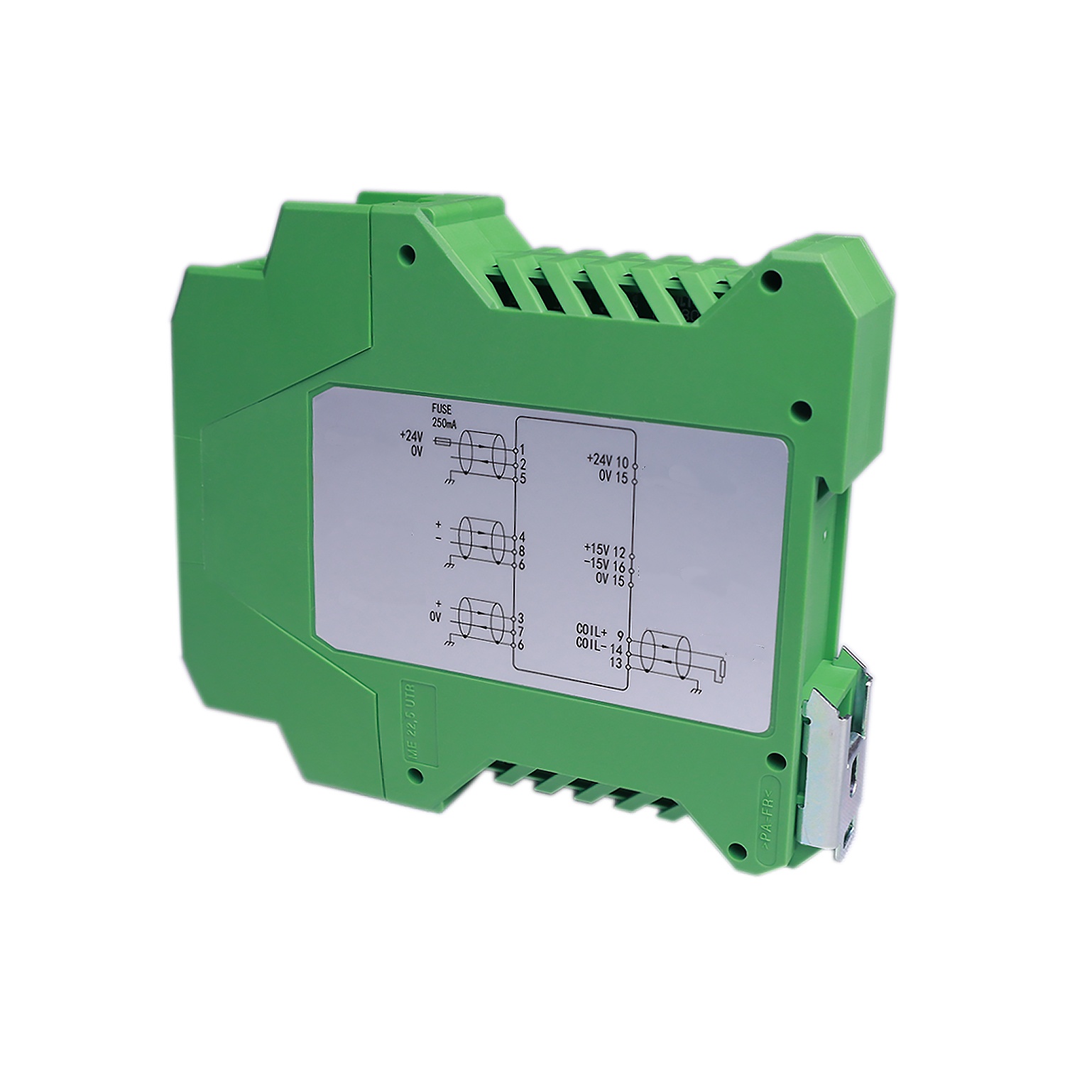
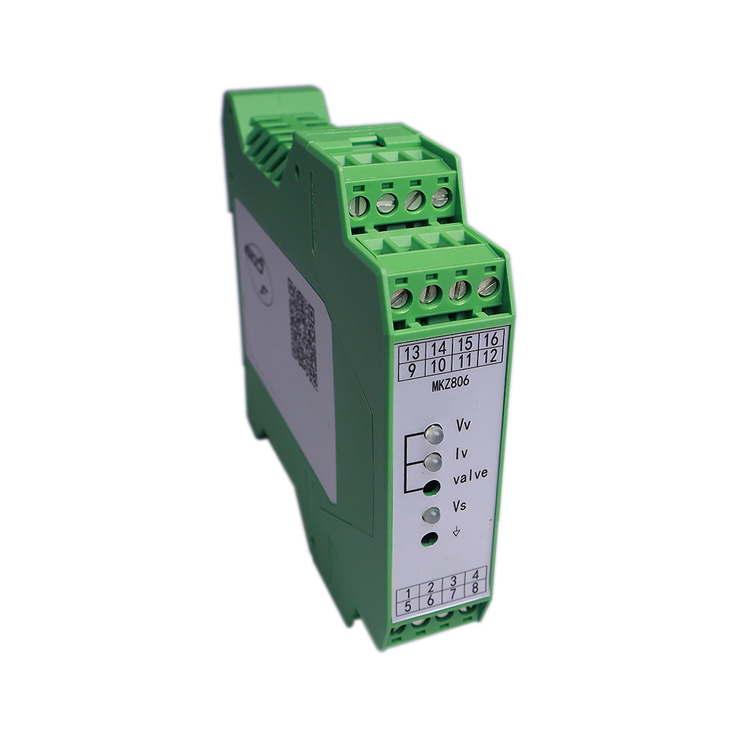
The finished appearance of the MKZ806 servo amplifier is shown in the external drawing. Its shell adopts a card type modular electronic shell, which is convenient for integrated installation and disassembly on standard DIN rails in various control cabinets. The main panel is equipped with working power supply, output signal status LED monitoring indicator lights, and testing sockets for easy debugging, fault diagnosis, and maintenance.
Technical Index :
Command Input Signal | 0~±10V;0~±10mA(±100mAmax);4~20 mA |
Output Signal | 0~±10V(Rt:1KQmin); 4~20mA(R:500Ωmax); 0~± 100mAmax (factory default setting ± 40mA)
I - Selected output current value Unit: A Ri - When selecting the output current value, the maximum load DC resistance value is measured in Ω ± 5mA, ± 10mA, ± 20mA, ± 30mA, ± 50mA current output switches are optional, and the desired output current value can also be obtained by combining the selection switches. For example, if the desired output current value is "± 85mA", the corresponding 5mA, 30mA, 50mA selection switches on the circuit board can be closed to use, and so on. |
Nonlinear | ≤1% |
Passband | ≥1000Hz(Do not use built-in low-pass filter) |
Output Signal Monitoring LED Light | Vv LED: ± 10V (maximum brightness) "+" - red "_" - green Iv LED: ± 5mA~± 100mA (maximum brightness) "+" - red "-" - green |
Wave Filter | Active first-order low-pass filter, with cutoff frequencies of 7, 16, 34, 72, 723Hz ± 10% switch options; The desired cutoff frequency value can be obtained by combining the selection switches |
Working Power Supply | 24VDC(22~28V)200mA; External fuse: 250mA (requires auxiliary power output -2.5A) |
Working Power Supply Monitor Vs LED Lights |
Power supply working normally - green |
Auxiliary Power Output | ±15V±110mAmax;24VDC 2Amax |
Installation Method | Standard DIN (35mm) rail card installation |
Protection Grade | IP20 |
Ambient Temperature | 0~40℃ |
Net Weight | 130g |
External Dimensions | 100W×108H×22.5DMM |