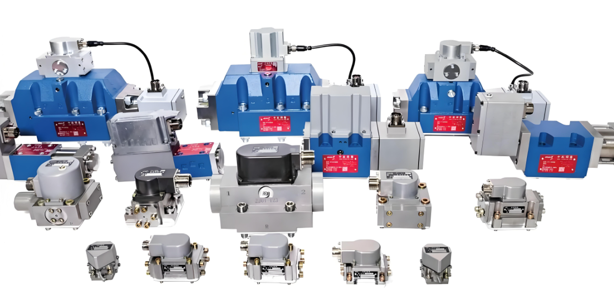
Electro-hydraulic valves represent the critical interface between electronic control systems and hydraulic power, enabling the precise and dynamic control of force, velocity, and position in modern machinery. They are the cornerstone of advanced automation, found in applications ranging from industrial robotics and injection molding machines to aerospace flight controls and material testing systems. This article provides an introduction to the two primary types: proportional and servo valves, explaining their working principles, key differences, and applications.
1. The Fundamental Principle: Converting Electrical Signals to Hydraulic Power
At their core, both proportional and servo valves operate on the same fundamental principle: they translate a low-power electrical input signal into a proportional, high-power hydraulic output—specifically, the control of flow rate (Q) or pressure (P).
This conversion is typically a two-stage process:
Electrical-to-Mechanical Force: An electromagnetic actuator (solenoid or torque motor) converts the incoming current into a mechanical force or displacement.
Hydraulic Amplification: This small mechanical action is used to pilot or directly control a larger, main-stage spool or poppet that meters high-pressure fluid to the actuator.
2. Proportional Valves: The Workhorses of Control
Proportional valves offer a middle ground between simple on/off solenoid valves and high-performance servo valves.
Working Principle: They use a proportional solenoid, which generates an output force proportional to the input current. This force directly positions the main spool against a spring. The spool's displacement, and consequently the size of the orifice through which fluid flows, is proportional to the current.
Key Characteristics:
Performance: They provide good control over speed and force but are limited by hysteresis and a less dynamic response compared to servo valves. Their accuracy is typically in the range of 2-5%.
Design: Often designed with a "proportional electromagnetic" and a spool with metering notches. Many modern proportional valves include an integrated electronic amplifier and an LVDT (Linear Variable Differential Transformer) for closed-loop spool position feedback, significantly improving their accuracy and repeatability.
Robustness: They are generally more tolerant of the contamination levels found in standard industrial environments.
Cost: Significantly less expensive than servo valves.
Example Application: Controlling the speed of a hydraulic press's approach stroke, regulating the tilt of a bulldozer blade, or managing the feed rate on a large machine tool.
3. Servo Valves: The Pinnacle of Precision
Servo valves are designed for the highest levels of precision, dynamic response, and closed-loop control. They are characterized by their ability to control very small flows with high accuracy and at very high frequencies.
Working Principle: They traditionally use a sensitive torque motor (a low-mass, permanent magnet motor) as the first stage. This torque motor deflects a tiny flapper, jet pipe, or nozzle baffle system, creating a small pilot pressure that acts on the ends of a second-stage spool. The spool's movement ports fluid to the actuator.
Key Characteristics:
Performance: Extremely high precision (hysteresis often<1%), very high frequency response (often over 100 Hz), and exceptional repeatability. They are designed for continuous, closed-loop control of position, velocity, or force.
Design: Feature complex multi-stage designs (typically two-stage). They almost always incorporate internal mechanical feedback, such as a feedback wire or spring, which precisely relates the main spool's position to the tiny input from the torque motor. This is what gives them their exceptional accuracy.
Sensitivity: Require very clean hydraulic fluid due to their extremely small internal orifices.
Cost: Considerably more expensive than proportional valves.
Example Application: Controlling the position of an aircraft wing flap, the motion of a industrial robot arm, the load in a structural test frame, or the cutter head on a tunnel boring machine.
4. Key Differences Between Proportional and Servo Valves
While the line has blurred with advanced proportional valves, the traditional distinctions remain:
Feature | Proportional Valves | Servo Valves |
|---|---|---|
Actuator | Proportional Solenoid | Torque Motor |
Typical Hysteresis | 2% - 5% | < 1% - 3% |
Frequency Response | 5 - 60 Hz | 50 - 250+ Hz |
Internal Feedback | Often an LVDT (electronic) | Mechanical feedback link (inherent) |
Contamination Tolerance | Good (ISO 18/16/13 typical) | Poor (Requires ISO 16/14/11 or better) |
Cost | Lower | Higher |
Application Focus | Less dynamic, open or closed-loop | Highly dynamic, precise closed-loop |
5. The Blurring Line: High-Performance Proportional Valves
Modern technology has given rise to "high-response proportional valves" or "servo-proportional valves." These valves combine the robust solenoid of a proportional valve with the sophisticated spool design and integrated electronic control of a servo valve. With an LVDT providing precise spool position feedback to the onboard electronics, their performance can approach that of traditional servo valves while maintaining better contamination tolerance and a lower cost.
Conclusion
The choice between a proportional and a servo valve is a fundamental design decision based on the requirements of performance, precision, dynamics, and cost.
Use proportional valves for applications where good, reliable control of speed or force is needed without the extreme dynamic requirements.
Use servo valves for the most demanding applications where utmost precision, high speed, and exceptional dynamic performance in a closed-loop system are non-negotiable.

